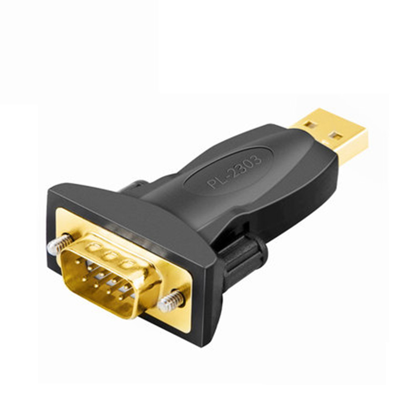
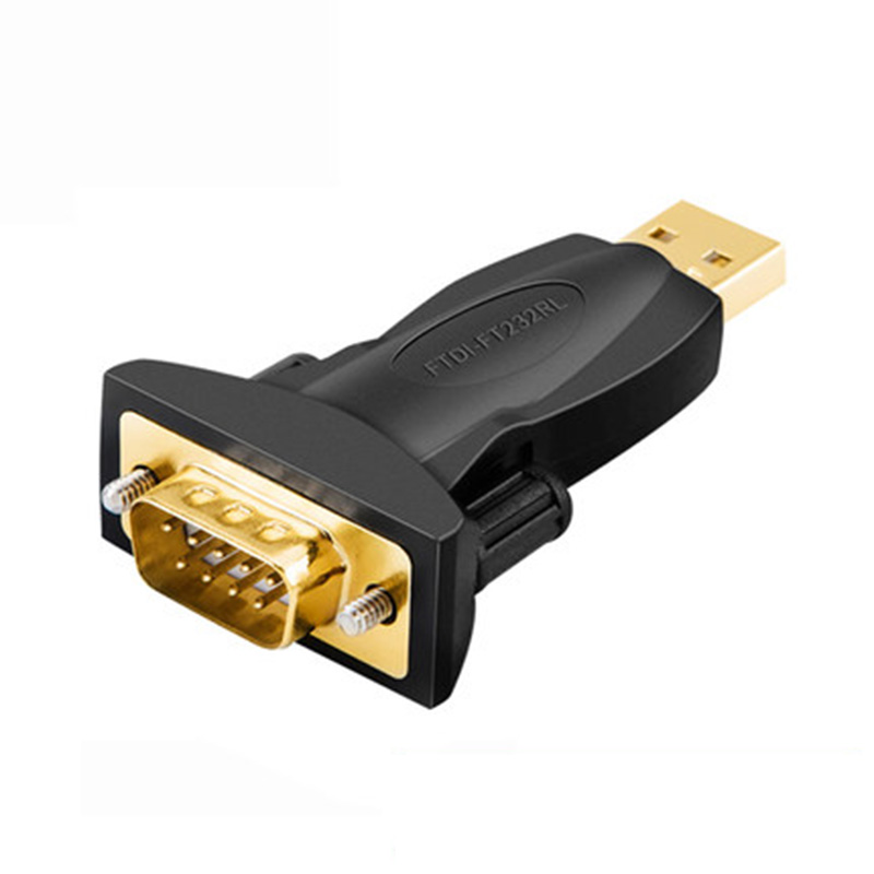
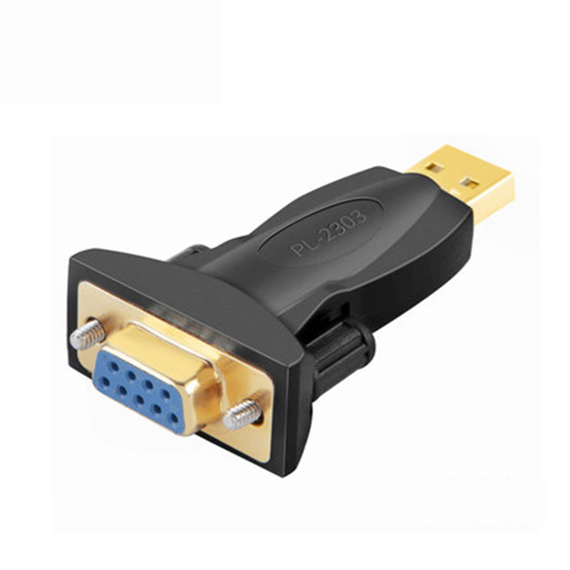
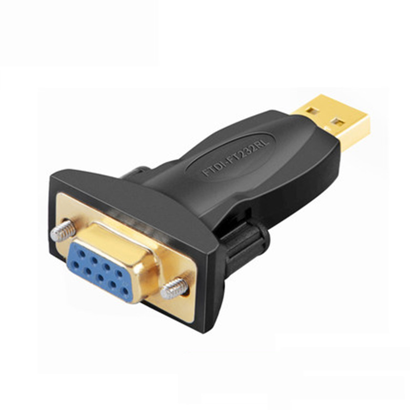
USB to DB9 Serial Adapter Gold Plated Male to Male Female RS232 FTDI PL2303 Converter Plug Adapter for Laptop Computer
USB 2.0 to DB9 RS232 Serial Adapter
Gold Plated
FTDI/FT232RL or PL2303 Chipset Optional
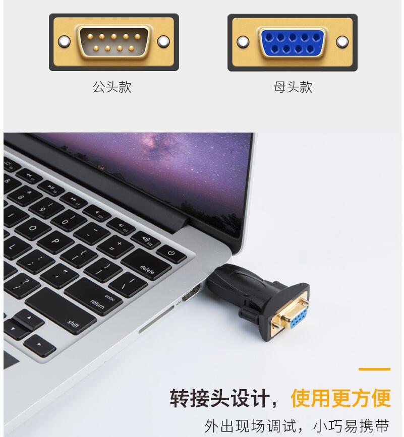
DB9 Male or Female optional
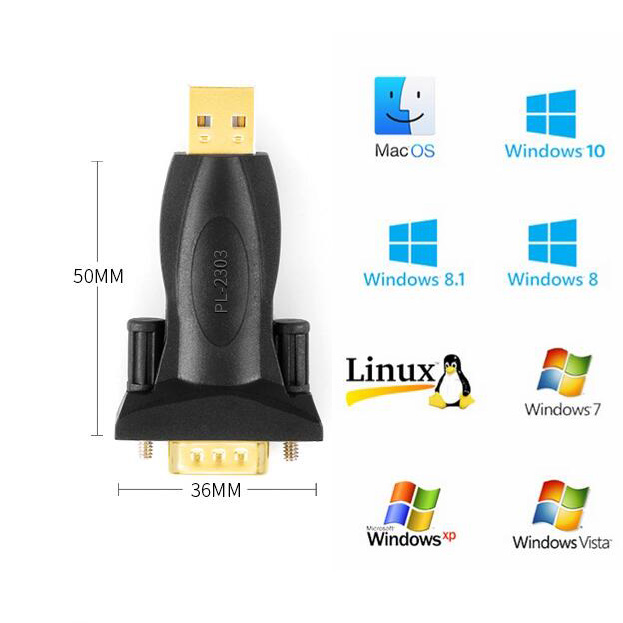
Systerm Support : For all windows, Vista , Linux, Mac , Android etc
Package : 1 X USB RS232 TO DB9 Adapter
1 X Mini CD software

PL2303TA provides a convenient solution for connecting an RS232-like full-duplex asynchronous serial device to any Universal Serial Bus (USB) capable host. PL2303TA highly compatible drivers could simulate the traditional COM port on most operating systems allowing the existing applications based on COM port to easily migrate and be made USB ready without having to rewrite the COM port software application.
By taking advantage of USB bulk transfer mode, large data buffers, and automatic flow control, PL2303TA is capable of achieving higher throughput compared to traditional UART (Universal Asynchronous Receiver Transmitter) ports.When real RS232 signaling is not required, baud rate higher than 115200 bps could be used for even higher performance. The flexible baud rate generator of PL2303TA could be programmed to generate any rate between 75 bps and 6M bps.
PL2303TA is exclusively designed for mobile and embedded solutions in mind, providing a small footprint that could easily fit in to any connectors and handheld devices. With very small power consumption in either operating or suspend mode, PL2303TA is perfect for bus powered operation with plenty of power left for the attached devices. Flexible signal level requirement on the RS232-like serial port side also allows PL2303TA to connect directly to any 3.3V~1.8V range devices.
Product Applications:
Single-chip upgrade solution for Legacy RS232 devices to USB interface
USB to RS232 converters/cables/dongles
Healthcare/Medical USB Interface Data Transfer Cable
Personal Infotainment/Media Player Docking USB Interface
Cellular/PDA USB Interface Data Transfer Cable
Serial-over-IP Wireless Solution
USB Barcode/Smart Card Readers
GPS/Navigation USB Interface
Point-of-Sale (POS) Terminals/Printers
PC Docking Station/Port Replicators
Industrial/Instrumentation/Automation Control USB Interface
USB Modem/Wireless/Zigbee USB Interface
Set-Top Box (STB) / Home Gateway USB Interface
BatteryCharger Application
MCU-based devices to USB interface
Windows Driver Installer Setup Program
(For PL2303 HXA, XA, HXD, EA, RA, SA, TA, TB versions)
Installer version & Build date: 1.9.0 (2013-10-25)
Windows XP (32 & 64-bit) WDM WHQL Driver: v2.1.51.238 (10/22/2013)
- Windows XP Certified WHQL Driver
- Compatible with Windows 2000SP4 & Server2003
Windows Vista/7/8/8.1 (32 & 64-bit) WDF WHQL Driver: v3.4.62.293 (10/17/2013)
- Windows Vista, 7, 8, 8.1 Certified WHQL Driver
- Compatible with Windows Server2008/Server2008R2/Server2012
- Driver can auto-download via Windows Update (for Windows Vista, 7, 8, 8.1)
Installer Language Support: English (default), Chinese (Traditional and Simplified), Japanese
For Prolific USB VID_067B&PID_2303 and PID_2304 Only
Includes Certification Report, User Manual & CheckChipVersion Tool
NOTE:
Windows 8/8.1 are NOT supported in PL-2303HXA and PL-2303X EOL chip versions.
Run PL2303 CheckChipVersion tool program in Windows XP/Vista/7 to check chip version.
Windows 98 and Windows ME driver support is discontinued and is no longer provided.
Prolific recommends to use PL-2303HXD (HX Rev D) or PL2303TA chip.
Installing the Plugable USB to RS-232 DB9 Serial Adapter on Windows 7
Windows 7 will detect and pop up a wizard to install drivers when the usb serial cable is plugged in, but it’s also easy (as essential on other operating systems) to install the driver software first.
You’ll want to download the driver and unzip it anywhere on your desktop. Once you have, double click on it to start the installation.
The installation is relatively simple and no questions are asked. When it’s done you should see something like this:
Now go ahead and connect the adapter. You should get a pop-up looking like this:
Finally Windows should report that the device has been installed:
On Device Manager you should be looking at something like this:
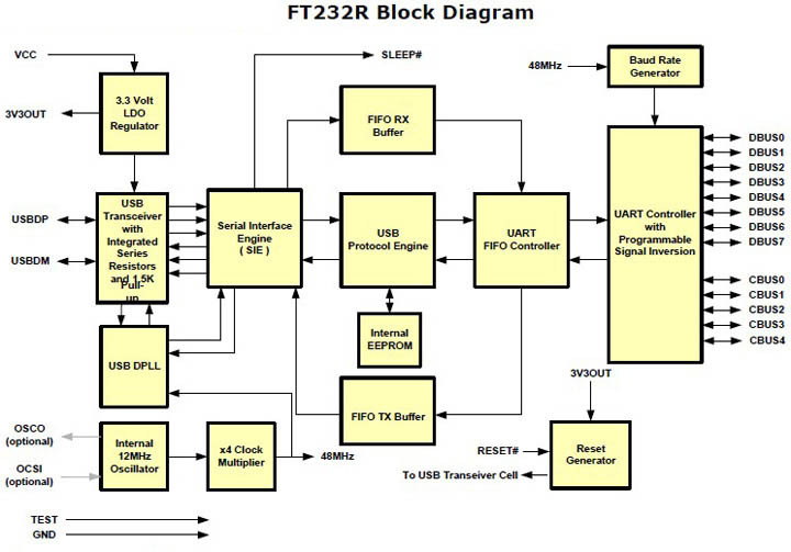
About FT232RL
The FT232R is the latest device to be added to FTDI?s range of USB UART interface Integrated Circuit Devices. The FT232R is a USB to serial UART interface with optional clock generator output, and the new FTDIChip-ID? security dongle feature. In addition, asynchronous and synchronous bit bang interface modes are available. USB to serial designs using the FT232R have been further simplified by fully integrating the external EEPROM, clock circuit and USB resistors onto the device.
The FT232R adds two new functions compared with its predecessors, effectively making it a "3-in-1" chip for some application areas. The internally generated clock (6MHz, 12MHz, 24MHz, and 48MHz) can be brought out of the device and used to drive a microcontroller or external logic. A unique number (the FTDIChip-ID?) is burnt into the device during manufacture and is readable over USB, thus forming the basis of a security dongle which can be used to protect customer application software from being copied.
Single chip USB to asynchronous serial data transfer interface.
Entire USB protocol handled on the chip - No USB-specific firmware programming required.
UART interface support for 7 or 8 data bits, 1 or 2 stop bits and odd / even / mark / space / no parity.
Fully assisted hardware or X-On / X-Off software handshaking.
Data transfer rates from 300 baud to 3 Megabaud (RS422 / RS485 and at TTL levels) and 300 baud to 1 Megabaud (RS232).
In-built support for event characters and line break condition.
New USB FTDIChip-ID? feature.
New configurable CBUS I/O pins.
Auto transmit buffer control for RS485 applications.
Transmit and receive LED drive signals.
New 48MHz, 24MHz,12MHz, and 6MHz clock output signal Options for driving external MCU or FPGA.
FIFO receive and transmit buffers for high data throughput.
256 Byte receive buffer and 128 Byte transmit buffer utilising buffer smoothing technology to allow for high data throughput.
Adjustable receive buffer timeout.
Synchronous and asynchronous bit bang mode interface options with RD# and WR# strobes.
New CBUS bit bang mode option.
Integrated 1024 bit internal EEPROM for I/O configuration and storing USB VID, PID, serial number and product description strings.
Device supplied preprogrammed with unique USB serial number.
Support for USB suspend / resume.
Support for bus powered, self powered, and high-power bus powered USB configurations.
Integrated 3.3V level converter for USB I/O .
Integrated level converter on UART and CBUS for interfacing to 5V - 1.8V Logic.
True 5V / 3.3V / 2.8V / 1.8V CMOS drive output and TTL input.
High I/O pin output drive option.
Integrated USB resistors.
Integrated power-on-reset circuit.
Fully integrated clock - no external crystal, oscillator, or resonator required.
Fully integrated AVCC supply filtering - No separate AVCC pin and no external R-C filter required.
UART signal inversion option.
USB bulk transfer mode.
3.3V to 5.25V Single Supply Operation.
Low operating and USB suspend current.
Low USB bandwidth consumption.
UHCI / OHCI / EHCI host controller compatible.
USB 2.0 Full Speed compatible.
-40°C to 85°C extended operating temperature range.
RS232 specifications, introduction
Communication as defined in the RS232 standard is an asynchronous serial communication method. The word serial means, that the information is sent one bit at a time. Asynchronous tells us that the information is not sent in predefined time slots. Data transfer can start at any given time and it is the task of the receiver to detect when a message starts and ends. Asynchronous communication has some advantages and disadvantages which are both discussed in the next paragraph.
RS232 bit streams
The RS232 standard describes a communication method where information is sent bit by bit on a physical channel. The information must be broken up in data words. The length of a data word is variable. On PC's a length between 5 and 8 bits can be selected. This length is the netto information length of each word. For proper transfer additional bits are added for synchronisation and error checking purposes. It is important, that the transmitter and receiver use the same number of bits. Otherwise, the data word may be misinterpreted, or not recognized at all.
With synchronous communication, a clock or trigger signal must be present which indicates the beginning of each transfer. The absence of a clock signal makes an asynchronous communication channel cheaper to operate. Less lines are necessary in the cable. A disadvantage is, that the receiver can start at the wrong moment receiving the information. Resynchronization is then needed which costs time. All data received in the resynchronization period is lost. Another disadvantage is that extra bits are needed in the data stream to indicate the start and end of useful information. These extra bits take up bandwidth.
Data bits are sent with a predefined frequency, the baud rate. Both the transmitter and receiver must be programmed to use the same bit frequency. After the first bit is received, the receiver calculates at which moments the other data bits will be received. It will check the line voltage levels at those moments.
With RS232, the line voltage level can have two states. The on state is also known as mark, the off state as space. No other line states are possible. When the line is idle, it is kept in the mark state.
Start bit
RS232 defines an asynchronous type of communication. This means, that sending of a data word can start on each moment. If starting at each moment is possible, this can pose some problems for the receiver to know which is the first bit to receive. To overcome this problem, each data word is started with an attention bit. This attention bit, also known as the start bit, is always identified by the space line level. Because the line is in mark state when idle, the start bit is easily recognized by the receiver.
Data bits
Directly following the start bit, the data bits are sent. A bit value 1 causes the line to go in mark state, the bit value 0 is represented by a space. The least significant bit is always the first bit sent.
Parity bit
For error detecting purposes, it is possible to add an extra bit to the data word automatically. The transmitter calculates the value of the bit depending on the information sent. The receiver performs the same calculation and checks if the actual parity bit value corresponds to the calculated value. This is further discussed in another paragraph.
Stop bits
Suppose that the receiver has missed the start bit because of noise on the transmission line. It started on the first following data bit with a space value. This causes garbled date to reach the receiver. A mechanism must be present to resynchronize the communication. To do this, framing is introduced. Framing means, that all the data bits and parity bit are contained in a frame of start and stop bits. The period of time lying between the start and stop bits is a constant defined by the baud rate and number of data and parity bits. The start bit has always space value, the stop bit always mark value. If the receiver detects a value other than mark when the stop bit should be present on the line, it knows that there is a synchronization failure. This causes a framing error condition in the receiving UART. The device then tries to resynchronize on new incomming bits.
For resynchronizing, the receiver scans the incomming data for valid start and stop bit pairs. This works, as long as there is enough variation in the bit patterns of the data words. If data value zero is sent repeatedly, resynchronization is not possible for example.
The stop bit identifying the end of a data frame can have different lengths. Actually, it is not a real bit but a minimum period of time the line must be idle (mark state) at the end of each word. On PC's this period can have three lengths: the time equal to 1, 1.5 or 2 bits. 1.5 bits is only used with data words of 5 bits length and 2 only for longer words. A stop bit length of 1 bit is possible for all data word sizes.
RS232 physical properties
The RS232 standard describes a communication method capable of communicating in different environments. This has had its impact on the maximum allowable voltages etc. on the pins. In the original definition, the technical possibilities of that time were taken into account. The maximum baud rate defined for example is 20 kbps. With current devices like the 16550A UART, maximum speeds of 1.5 Mbps are allowed.
Voltages
The signal level of the RS232 pins can have two states. A high bit, or mark state is identified by a negative voltage and a low bit or space state uses a positive value. This might be a bit confusing, because in normal circumstances, high logical values are defined by high voltages also. The voltage limits are shown below.
RS232 voltage values Level Transmitter
capable (V) Receiver
capable (V)
Space state (0) +5 ... +15 +3 ... +25
Mark state (1) -5 ... -15 -3 ... -25
Undefined - -3 ... +3
More information about the voltage levels of RS232 and other serial interfaces can be found in the interface comparison table.
The maximum voltage swing the computer can generate on its port can have influence on the maximum cable length and communication speed that is allowed. Also, if the voltage difference is small, data distortion will occur sooner. For example, my laptop mark's voltage is -9.3 V, compared to -11.5 V on my desktop computer. The laptop has difficulties to communicate with Mitsubishi PLC's in industrial environments with high noise levels where the desktop computer has no data errors at all using the same cable. Thus, even far beyond the minimum voltage levels, 2 volts extra can make a huge difference in communication quality.
Despite the high voltages present, it is not possible to destroy the serial port by short circuiting. Only applying external voltages with high currents may eventually burn out the driver chips. Still then, the UART won't be damaged in most cases.
Maximum cable lengths
Cable length is one of the most discussed items in RS232 world. The standard has a clear answer, the maximum cable length is 50 feet, or the cable length equal to a capacitance of 2500 pF. The latter rule is often forgotten. This means that using a cable with low capacitance allows you to span longer distances without going beyond the limitations of the standard. If for example UTP CAT-5 cable is used with a typical capacitance of 17 pF/ft, the maximum allowed cable length is 147 feet.
The cable length mentioned in the standard allows maximum communication speed to occur. If speed is reduced by a factor 2 or 4, the maximum length increases dramatically. Texas Instruments has done some practical experiments years ago at different baud rates to test the maximum allowed cable lengths. Keep in mind, that the RS232 standard was originally developed for 20 kbps. By halving the maximum communication speed, the allowed cable length increases a factor ten!
RS232 cable length according to Texas Instruments Baud rate Maximum cable length (ft)
19200 50
9600 500
4800 1000
2400 3000
Error detection
One way of detecting errors is already discussed. It is the frame detection mechanism which is used to test if the incomming bits were properly surrounded by a start and stop bit pair. For further error checking, a parity bit can be used. The use of this bit is however not mandatory. If the existence of wrong bits is rare (when communicating with an internal modem for example) or if a higher level protocol is used for error detection and correction (Z-modem, RAS, etc) communication speed can be increased by not using the parity feature present on the UART.
Parity is a simple way to encode a data word to have a mechanism to detect an error in the information. The method used with serial communications adds one bit to each data word. The value of this bit depends on the value of the data word. It is necessary that both the transmitter and receiver use the same algorithm to calculate the value of the parity bit. Otherwise, the receiver may detect errors which are not present.
Even parity
Basically, the parity bit can be calculated in two ways. When even parity is used, the number of information bits sent will always contain an even number of logical 1's. If the number of high data bits is odd, a high value parity bit is added, otherwise a low bit will be used.
Odd parity
The odd parity system is quite similar to the even parity system, but in this situation, the number of high bits will always be odd.
Disadvantages of the parity system
The parity system using one bit for each data word is not capable of finding all errors. Only errors which cause an odd number of bits to flip will be detected. The second problem is, that there is no way to know which bit is false. If necessary, a higher level protocol is necessary to inform the sender that this information must be resent. Therefore, on noisy lines, often other detection systems are used to assure that the sent information is received correctly. These systems mostly do not operate on single data words, but on groups of words

>> Shipping & Handling
1. Processing Time: 1-3 days for all orders.
2. Special Requests: Please list your special requests (color, package, etc) in the Notes Section when check out.
3. Shipping Way: Most orders(less than 2KG) are shipped by Aliexpress standard shipping / Netherland Post / Swiss Post
Under $5 orders are shipped by Seller Method Shipping.
Any other requirements about the shipping way, please contact us.
4. Delivery Time: Normally 15-60 days to get the order, except Brazil.Sometime the transit time may be long and vary,particularly during the holiday season.
Please contact us if you need help for the tracking.
5. Import Duties: Import duties, taxes and charges are not included in the item price or shipping charges.
>> Return & Refund
Return Policy: We accept Aliexpress return policy; Buyer pays return shipping.
Refund Policy: We provide reliable service policy.
• If you receive the goods broken. Contact us for Full money refund or replacement.
• If you don't receive the goods in stated delivery time. Contact us for Full money refund or replacement.
• If you receive the goods with quality problem, contact us for half or full amount refund.
• Any disatified with the product, please contact us first instead to open dispute or leave negative feedback.
>> Feedback
If you are satisfied with the item while it is in good condition, we sincerely to invite you to leave us all 5-star rating positive feedback.
If you are disatisfied with the item or service, please contact us first, we will supply the best solution and work harder to give you more excellent service.


